

Blog
Estrategias para evitar el sobrecorte en las esquinas y el levantamiento del cuchillo al cortar fundas de asiento de cuero genuino con cuchillos redondos.

Strategies to avoid corner overcut and knife lift when cutting genuine leather seat covers with round knives
I've seen countless seat cover manufacturers waste expensive leather testing random parameter changes that make problems worse instead of better. The hardest part isn't fixing corner overcut and knife lift — it's diagnosing which root cause you're actually fighting.
Corner overcut and knife lift stem from multi-parameter coupling issues where blade pressure, motion speed, acceleration curves, and leather rebound characteristics interact simultaneously. Most troubleshooting fails because clients test wrong parameters in wrong order, misdiagnosing symptom-cause relationships and creating secondary cutting defects.
After supporting hundreds of automotive seat cover cutting projects, I've noticed the same pattern: clients jump to speed reduction or blade replacement without checking which specific failure mode they're dealing with. Let me walk you through the diagnostic sequences that actually minimize material waste.
What causes corner overcut when your round knife cuts genuine leather?
Corner overcut happens when your blade travels beyond the programmed cutting path at directional change points. I see this almost weekly during on-site commissioning.
Corner overcut occurs when deceleration distance at directional changes is insufficient for blade momentum, or when corner radius compensation algorithms don't match leather elastic rebound behavior. The blade physically overshoots the programmed path before the motion controller completes directional change.
The first mistake I see is clients assuming this is purely a speed problem. In our after-sales cases, we found corner overcut involves at least four interacting variables: cutting speed at corner entry, acceleration/deceleration curve shape, corner radius size in toolpath, and blade downforce during directional change. Lowering speed alone often fails because it doesn't address momentum transfer issues or elastic rebound timing.
When I diagnose corner overcut on-site, I check the cut edge characteristics first. If the overcut distance increases proportionally with corner sharpness (smaller radius = worse overcut), the root cause is insufficient deceleration. If overcut distance stays constant regardless of corner radius, the cause is usually blade pressure imbalance during directional change. If you see material bunching or wrinkling at corner exit points, leather elastic rebound is fighting your motion timing.
Here's the parameter testing sequence that works:
| Test sequence | Parameter to adjust | Expected symptom change | Confirms root cause |
|---|---|---|---|
| Step 1 | Reduce corner entry speed by 30% | Overcut distance decreases proportionally | Insufficient deceleration time |
| Step 2 | Increase deceleration zone length by 50% | Overcut disappears at larger corners first | Acceleration curve mismatch |
| Step 3 | Reduce blade pressure by 15% at corners | Material bunching reduces, overcut persists | Elastic rebound interference |
| Step 4 | Enable corner radius compensation +0.3mm | Overcut shifts from outside to inside curve | Toolpath geometry issue |
The critical mistake is testing Step 4 before Step 1. Many clients enable corner compensation algorithms immediately, which masks the actual root cause and creates inside-corner undercut problems later. I always verify deceleration sufficiency first because it's the most common genuine cause.
For different leather types, the adjustment ranges change significantly. When cutting soft nappa leather (0.8-1.0mm thickness), I typically set corner entry speed at 40-50% of straight-line speed. For firmer full-grain leather (1.2-1.5mm thickness), corner speed can stay at 60-70% of baseline because material rebound is less pronounced. The hardness difference matters more than thickness alone.
One pattern I've noticed: if your overcut only appears after 2-3 hours of continuous cutting, blade temperature expansion is changing your effective blade pressure. This isn't a parameter issue — your cooling system needs adjustment or your blade holder has thermal drift problems.
Why does knife lift happen mid-cut when processing automotive leather?
Knife lift is when your blade loses contact with the cutting mat during the cut, creating incomplete penetration or rough edges. This problem frustrates clients more than overcut because the failure mode seems random.
Knife lift occurs when vertical downforce becomes insufficient to overcome leather elastic resistance and material rebound forces during blade motion. The blade physically rises above full penetration depth, especially at direction changes or when encountering fiber density variations within the leather hide.
The most common misdiagnosis I encounter is clients assuming blade dullness causes lift. While worn blades do reduce cutting efficiency, true knife lift happens even with new blades if the root cause is downforce insufficiency or material elasticity mismatch. When we diagnose this symptom on-site, we check blade wear patterns first, but we don't replace the blade until we verify the actual failure mechanism.
Here's how to distinguish blade issues from parameter issues from material issues by examining the cut edge:
If you see inconsistent penetration depth that follows leather surface texture (deeper cuts in softer areas, shallower in firmer zones), the cause is insufficient downforce for material hardness variation. If penetration depth is consistent but edge quality degrades progressively over 30-60 minutes, blade dulling is the primary cause. If lift only occurs at corners or curve entry points, motion acceleration is pulling the blade upward against insufficient clamping force.
The diagnostic sequence I use minimizes material waste:
| Diagnostic step | What to check | How to verify | Root cause confirmed |
|---|---|---|---|
| Step 1 | Blade tip condition under 10x magnification | Look for rounded tip or lateral micro-chips | Blade wear (replace blade) |
| Step 2 | Penetration depth at straight sections vs. corners | Measure with depth gauge on scrap cuts | Motion-induced lift (adjust acceleration) |
| Step 3 | Cut quality variation across single hide | Map failure locations to leather surface zones | Material hardness variation (increase baseline pressure) |
| Step 4 | Lift occurrence timing (immediate vs. delayed) | Note when lift starts after blade installation | Thermal drift or pressure calibration drift |
I always test Step 1 first because blade inspection costs nothing. Many clients waste expensive leather testing parameter changes when a simple blade replacement would solve the problem immediately. But I've also seen the opposite: clients replace blades repeatedly without fixing the actual downforce insufficiency, burning through blade inventory needlessly.
For parameter adjustment ranges that actually work, I follow these boundaries based on leather characteristics:
When cutting soft automotive leather (like perforated seat surfaces), increase blade pressure by 10-15% over your baseline setting. When cutting firm leather (like seat side panels or lumbar support areas), increase pressure by 20-30%. These ranges assume your baseline pressure already achieves clean cuts on uniform test materials. If you're starting from scratch, establish baseline first by cutting 200mm straight lines on scrap leather at incrementally higher pressures until you achieve clean penetration without material compression.
One critical parameter clients overlook is blade oscillation frequency. If your round knife uses oscillating blade motion (most automotive leather cutters do), insufficient oscillation amplitude during high-speed cutting reduces effective penetration. When I encounter lift issues during curve cutting but not straight cuts, I increase oscillation amplitude by 5-10% before touching pressure settings. This solves the problem about 40% of the time without increasing mat wear from excessive pressure.
Material-specific strategy selection depends on leather fiber structure. Chrome-tanned automotive leather (most seat covers) has tight fiber structure with high rebound elasticity. For this material type, I prioritize blade pressure adjustment over speed reduction because the elastic rebound force is the primary resistance. Vegetable-tanned leather (less common in automotive applications but used in luxury interiors) has looser fiber structure with lower rebound. For vegetable-tanned materials, I prioritize speed reduction over pressure increase because excessive pressure causes fiber compression and edge roughness.
The interaction between lift and overcut creates a diagnostic trap. If you increase blade pressure to solve lift, you often worsen corner overcut because higher pressure increases friction and momentum at directional changes. The correct approach is to solve lift first with minimum pressure increase necessary, then address any resulting overcut through deceleration curve adjustment. Testing in reverse order creates a parameter spiral where each adjustment makes the other problem worse.
How do acceleration and deceleration curves affect corner cutting quality?
Acceleration and deceleration curves control how quickly your cutting head changes speed when entering and exiting corners. Most clients never adjust these parameters because they seem too technical.
Acceleration and deceleration curves determine the distance and time span over which your cutting head transitions between speeds. Aggressive curves (short transition distance) cause momentum-based overcut and blade lift at corners. Gentle curves (long transition distance) reduce corner defects but decrease overall cutting efficiency and throughput.
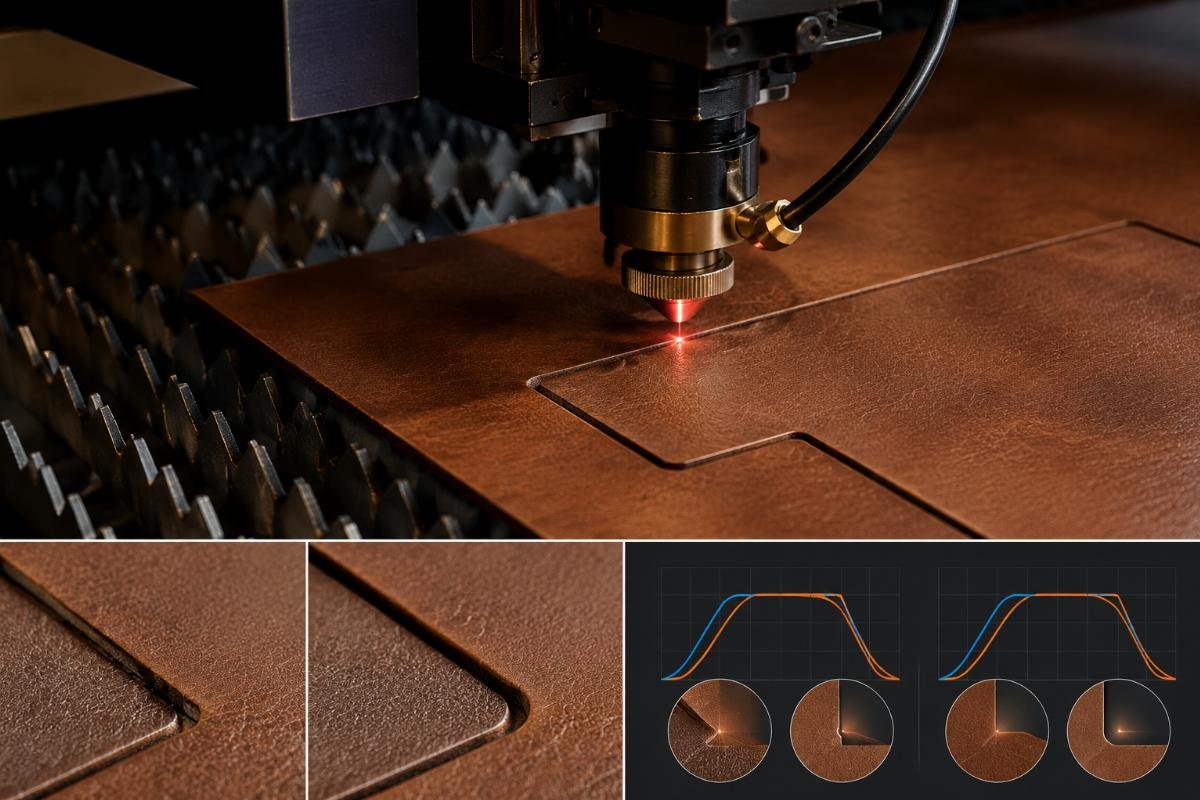
When we diagnose corner quality issues on-site, we examine the acceleration curve settings after verifying blade condition and baseline pressure. The reason is simple: acceleration curves are the bridge parameter that connects speed settings to actual cutting behavior. You can set perfect corner speeds, but if your deceleration curve is too aggressive, the cutting head won't reach target corner speed until after entering the corner radius.
The relationship between curve shape and corner defect type follows predictable patterns. S-curve acceleration (gentle start, steep middle, gentle end) produces the best corner quality for automotive leather because it minimizes jerk forces that lift the blade. Linear acceleration (constant rate of speed change) works acceptably for loose-tolerance applications but creates noticeable overcut at sharp corners. Trapezoidal acceleration (aggressive ramp-up, constant speed, aggressive ramp-down) should be avoided for genuine leather — I only see this curve setting work on synthetic materials with minimal elastic rebound.
Here's the adjustment strategy that minimizes trial-and-error cycles:
| Current corner defect | Acceleration curve adjustment | Deceleration curve adjustment | Expected result |
|---|---|---|---|
| Overcut on corner exit | No change needed | Extend deceleration zone by 50% | Earlier speed reduction before corner entry |
| Overcut on corner entry | Extend acceleration zone by 30% | Extend deceleration zone by 50% | Smoother speed transitions both directions |
| Blade lift at corner apex | Switch to S-curve if using linear | Reduce deceleration rate by 20% | Less vertical jerk force during transition |
| Material bunching after corners | Reduce acceleration rate by 20% | No change needed | Less tensile force pulling material during exit |
The numbers in this table assume your controller allows curve shape modification. If your machine only offers acceleration/deceleration time adjustment (common in older CNC systems), increase time values by 30-50% to achieve similar effect to extending zone length or reducing rate.
One mistake I see repeatedly is clients adjusting acceleration and deceleration symmetrically. In automotive leather cutting, deceleration curve matters more than acceleration curve because leather elastic rebound affects corner entry more severely than corner exit. When I'm optimizing corner quality with limited testing time, I focus 80% of adjustment effort on deceleration parameters and only tune acceleration if corner exit defects persist.
The interaction between curve settings and leather thickness creates non-intuitive behavior. Thicker leather (1.5mm+) needs gentler deceleration curves than thin leather (0.8mm) because elastic rebound force increases with material thickness. But thicker leather also tolerates faster acceleration on corner exit because greater material mass resists bunching. This means optimal curve settings are asymmetric: gentle deceleration, moderate acceleration.
When corner radius in your toolpath becomes smaller than 5mm (common in automotive seat cover designs with tight curves), curve-based solutions reach their limit. At extremely sharp corners, even perfect acceleration curves can't prevent some overcut because blade geometry itself has physical turning radius. For these cases, I recommend enabling corner loop compensation if your controller supports it — the blade makes a small loop movement at the corner apex to maintain cutting pressure through the directional change. This feature adds cycle time but eliminates overcut at radii below 5mm.
When should you enable corner compensation algorithms versus manual tuning?
Corner compensation algorithms are controller features that automatically adjust cutting parameters at corners based on radius detection. Many clients don't know when to use them.
Corner compensation algorithms should be enabled when your cutting patterns contain mixed corner radii (both large and small) within single parts, or when leather material characteristics vary significantly across production batches. Manual parameter tuning works better when corner radii are consistent or when you need maximum cutting speed on simple geometries.
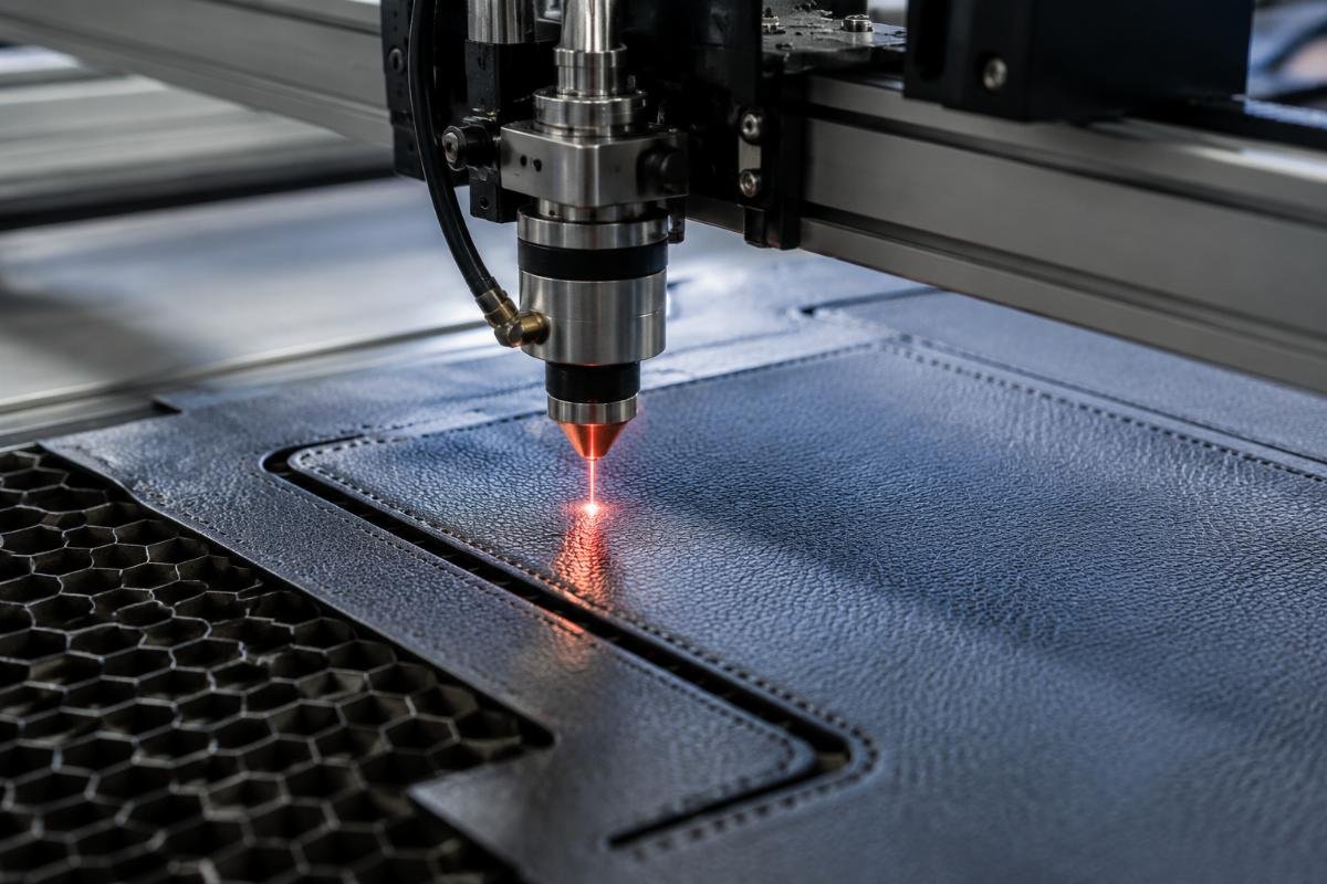
In our after-sales cases, we found that corner compensation algorithms solve different problems than manual tuning. Algorithms dynamically adjust speed, pressure, and sometimes toolpath based on real-time radius calculation. Manual tuning applies fixed parameter changes to all corners regardless of geometry. Neither approach is universally superior — the right choice depends on your specific production scenario.
Here's when each approach works best:
Use corner compensation algorithms when:
- Your seat cover designs mix tight curves (radius under 10mm) with gentle curves (radius over 30mm) in the same cutting file
- You process multiple leather types daily with different hardness and rebound characteristics
- Your operators don't have time or expertise to optimize parameters for each job
- Production volume justifies the 10-15% cycle time increase that algorithms typically add
Use manual parameter tuning when:
- Your seat cover designs use consistent corner radii throughout (common in standardized automotive models)
- You process the same leather specification for weeks or months at a time
- Your operators are experienced and can recognize which parameters need adjustment
- Cycle time is critical and you can't accept algorithm overhead
The decision isn't permanent. I've helped clients start with manual tuning during production ramp-up when they're learning their material characteristics, then switch to algorithms once production volume increases and operator time becomes the bottleneck.
One pattern I've noticed: corner compensation algorithms work poorly on leather with extreme fiber direction variation. The algorithm assumes homogeneous material properties, but genuine leather has fiber direction changes that affect cutting resistance unpredictably. When we encounter corner quality issues that persist even with algorithms enabled, we usually find that fiber direction at corners is fighting the blade motion. For these cases, manual pre-compensation in your CAD/CAM toolpath (adding slight radius enlargement before generating cutting code) works better than relying on real-time controller compensation.
The adjustment workflow differs significantly between approaches. With manual tuning, you test parameters on scrap material, identify optimal settings, then apply them globally. With algorithms, you test activation of different compensation features (radius-based speed reduction, pressure modulation, toolpath offset) and configure threshold values where compensation triggers. Algorithm configuration takes longer initially but requires less per-job adjustment.
I always recommend starting with algorithms disabled during initial setup. This lets you establish baseline cutting behavior without algorithm interference masking parameter problems. Once you achieve acceptable straight-line cutting and gentle-curve quality, enable algorithms and test their effect on sharp corners specifically. If algorithm activation solves sharp-corner problems without degrading gentle-curve quality, keep it enabled. If algorithm activation creates new problems (common symptoms: inside-corner undercut, excessive cycle time, inconsistent cut depth), revert to manual tuning and address sharp corners through toolpath pre-compensation instead.
How does leather fiber direction interact with cutting parameters?
Leather fiber direction determines material resistance direction during cutting. Most clients don't consider fiber direction when troubleshooting corner defects, but it's often the hidden variable that makes "identical" cuts behave differently.
Leather fiber direction creates anisotropic cutting resistance where blade motion parallel to fibers encounters less resistance than perpendicular motion. At corners, fiber direction changes relative to blade motion direction, causing sudden resistance changes that manifest as overcut or lift if parameters don't accommodate the transition.
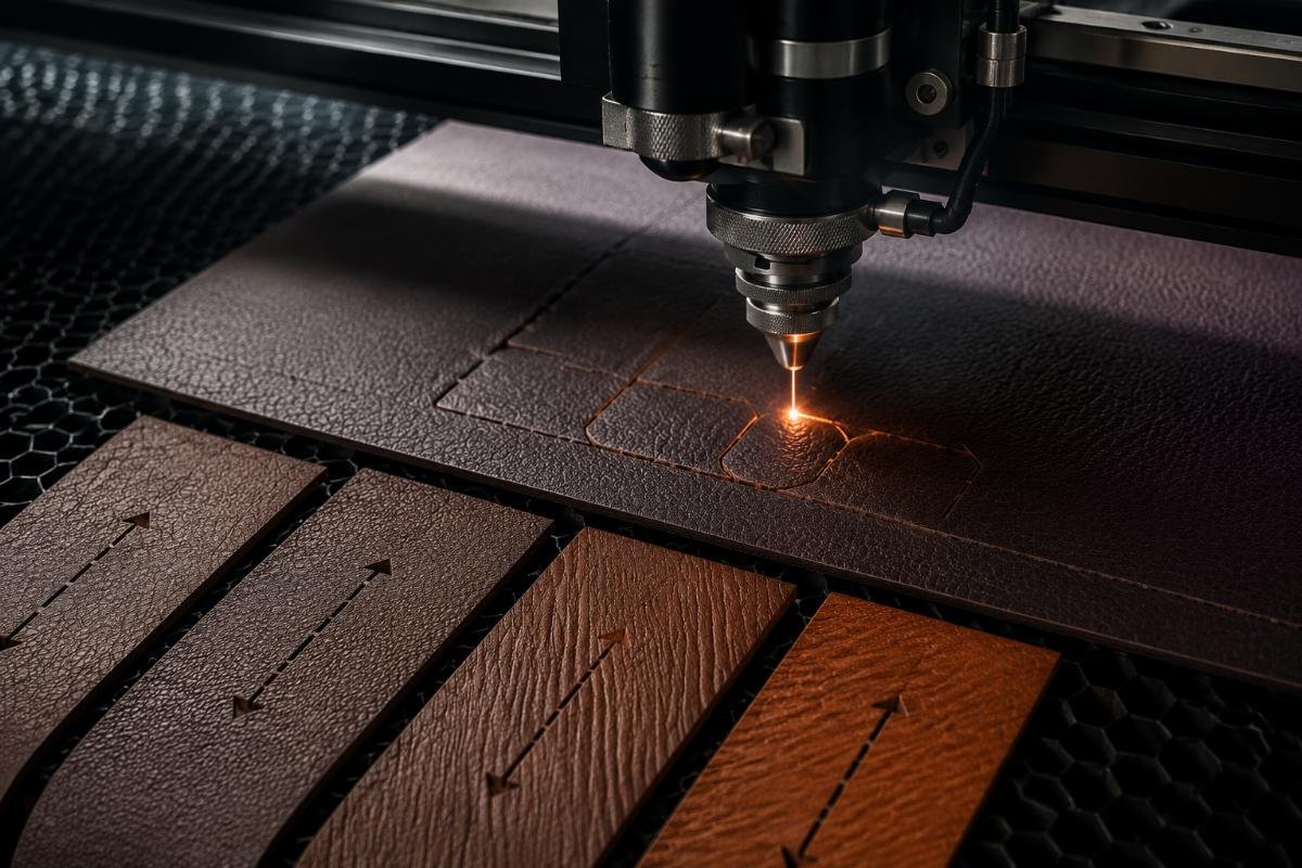
When I diagnose corner quality issues that appear random (good corners and bad corners in the same cutting file on the same material), fiber direction interaction is usually the cause. The problem is invisible in your parameter settings because fiber direction isn't a machine parameter — it's a material property that changes position relative to your toolpath depending on how the hide is placed on the cutting table.
The fiber direction effect follows predictable patterns. When your blade cuts parallel to fiber direction (along the backbone line of the hide), cutting resistance is minimal and standard parameters work well. When the blade cuts perpendicular to fibers (across the hide width), resistance increases 30-50% and you need higher blade pressure or slower speed to maintain quality. At corners where blade direction transitions from parallel to perpendicular cutting, resistance changes abruptly and causes the blade to either overcut (if momentum overcomes suddenly-higher resistance) or lift (if downforce is insufficient for suddenly-higher resistance).
Here's how fiber direction manifests in different corner defect patterns:
| Defect symptom | Fiber direction relationship | Adjustment strategy | Why this works |
|---|---|---|---|
| Overcut when entering corners | Corner entry transitions from parallel to perpendicular cutting | Reduce corner entry speed by additional 15% | Compensates for resistance spike during transition |
| Lift when exiting corners | Corner exit transitions from perpendicular to parallel cutting | Maintain higher blade pressure through entire corner | Prevents pressure drop from being too sudden |
| Inconsistent corner quality on same part | Part orientation changes relative to fiber direction between cuts | Use nesting software with fiber direction consideration | Aligns part orientation to minimize perpendicular cutting |
| Good corners on one side of hide, bad corners on other side | Natural fiber direction asymmetry in hide | Map fiber direction before cutting, |