

Blog
Can Car Interiors CNC Cutting Machines Successfully Cut Lightweight Composite Materials Like Teslin and Hemp Fiber Boards for New Energy Vehicles?

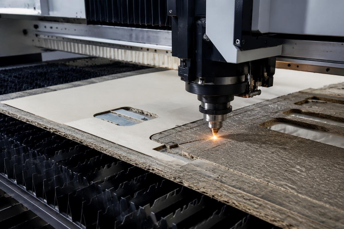
Can Car Interiors CNC Cutting Machines Successfully Cut Lightweight Composite Materials Like Teslin and Hemp Fiber Boards for New Energy Vehicles?
I receive this question almost weekly from NEV interior suppliers1. They've already chosen Teslin or hemp fiber boards as their lightweight solution. Now they need to know if their current cutting equipment can handle it—or if they must invest in new machines. The real problem isn't the material itself. It's the gap between what suppliers promise and what actually happens on your production floor.
Yes, CNC cutting machines can process Teslin and hemp fiber boards, but success depends on matching equipment capabilities to your material's specific layering structure, fiber orientation, and required edge finish—not just advertised specs. Most failures occur because buyers test under ideal conditions that don't match real production variables.
Before I explain the verification framework we developed from customer feedback, you need to understand why this isn't a simple yes-or-no question. The answer changes based on your tolerance for edge defects, production speed requirements, and how much variation exists in your material batches.
Why Do Buyers Get Misleading Answers About Cutting Capability for These Materials?
Most suppliers answer based on maximum thickness capacity or material categories listed in their spec sheets. This creates false confidence. I've seen customers purchase machines rated for "composite materials up to 50mm" only to discover fiber fraying issues at 8mm when cutting hemp fiber boards with cross-directional weaving patterns.
The misleading answer happens because equipment specs describe ideal conditions—uniform density, consistent fiber orientation, and single-material composition—while your actual production involves layered structures, thickness variations, and mixed fiber directions that behave completely differently under blade pressure.
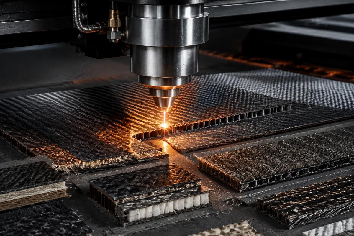
What Are the Real Variables That Determine Success or Failure?
Let me break down what actually matters based on failure reports from our customers:
Material structure variables:
| Variable | Impact on Cutting | Common Failure Point |
|---|---|---|
| Fiber orientation | Determines blade entry angle requirements | Cross-grain cuts cause fraying when blade angle isn't adjusted |
| Layer bonding strength | Affects delamination risk during cutting | Weak adhesive layers separate under blade vibration |
| Thickness tolerance | Changes cutting depth consistency | ±0.5mm variation causes incomplete cuts or over-penetration2 |
| Surface coating | Influences tool dulling rate | Protective coatings accelerate blade wear without parameter adjustment |
One customer processing Teslin for dashboard components reported edge fraying after 200 cuts. When we reviewed their setup, they were using blade angles optimized for single-layer materials. Teslin's woven structure required shallower blade entry and slower traverse speed3. After adjustment, fraying disappeared. The machine didn't change. The parameters did.
Task requirement variables:
Your acceptable failure rate determines equipment selection more than material type. If you need zero edge defects for visible interior panels, you'll need different validation steps than someone cutting hidden structural components where small fiber protrusion is acceptable.
Boundary testing conditions:
We discovered that successful material processing depends on testing under conditions that match your worst-case production scenario—not your average material. Test with your thickest samples. Test with maximum fiber density variations. Test after continuous eight-hour runs when blade dulling becomes significant.
What Are the Most Common Failure Scenarios Customers Report When Cutting These Lightweight Composites?
I track failure reports from NEV suppliers because they reveal the gap between test cutting and production reality. Four patterns appear repeatedly. Understanding these helps you structure your verification testing before purchase.
Fiber fraying on cut edges happens when blade sharpness, cutting speed, or blade angle don't match material fiber density and orientation. This is the most reported issue with hemp fiber boards.
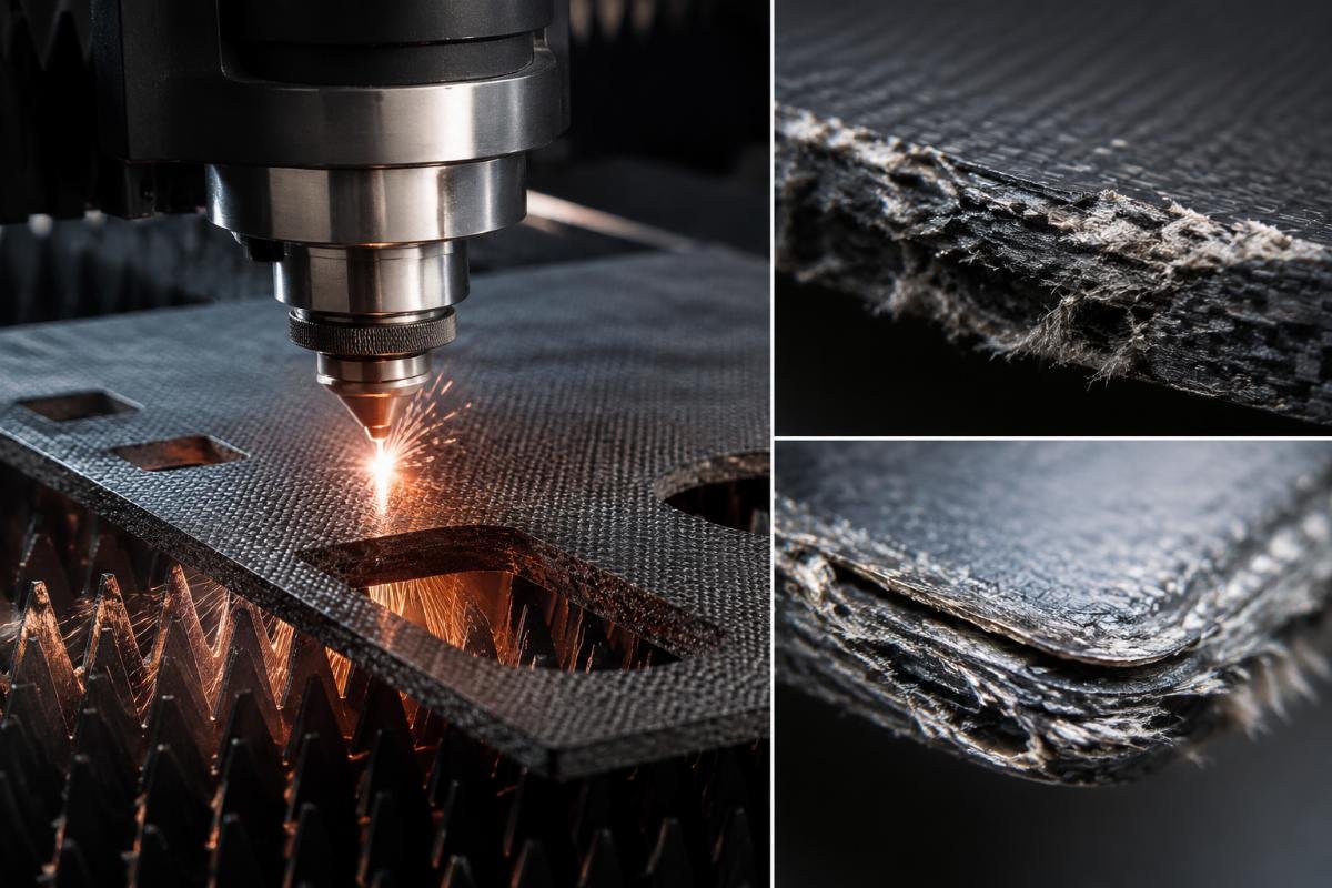
How Does Fiber Fraying Occur and When Does It Become Unacceptable?
Fraying occurs when individual fibers aren't cleanly severed. Instead, they bend away from the blade path and break at irregular lengths. For hemp fiber boards, this happens most often at direction changes—curves, corners, or acute angles—where blade pressure shifts.
The question isn't whether fraying will occur. It's whether the amount of fraying exceeds your quality standards. One customer producing door panel components accepts fraying up to 0.3mm because their assembly process includes edge wrapping. Another customer making dashboard trim rejects any visible fraying because edges remain exposed.
Testing framework for fraying:
- Cut your most complex shape with tightest curves
- Measure maximum fiber protrusion under 10x magnification
- Compare to your quality acceptance criteria
- Document blade condition (new vs. after 500 cuts)
- Repeat test with fiber direction rotated 90 degrees
What Causes Delamination Between Composite Layers?
Delamination happens when layers separate during or immediately after cutting. I see this most frequently with Teslin materials that combine different fiber types in alternating layers. The blade creates vibration that exceeds the bonding strength between layers.
Three conditions increase delamination risk:
Vacuum hold strength insufficient for material flexibility: Thin composite boards (under 5mm) often flex during cutting. If vacuum pressure doesn't firmly hold the material against the cutting table, blade pressure causes the top layer to lift slightly. This creates shear force at the bonding interface. The layers separate.
Blade dullness increases cutting force beyond bonding strength: A sharp blade slices through. A dull blade pushes and tears. When cutting force increases, the bonding adhesive between layers fails. We've documented cases where delamination appeared after 300 cuts with the same blade—not because the machine changed, but because blade sharpness degraded.
Multi-pass cutting amplifies stress at layer boundaries: Some operators attempt to reduce fraying by using multiple shallow passes instead of single-pass full-depth cutting. This strategy works for single-layer materials. For composites, each pass introduces new stress cycles at the bonding interface. Delamination risk increases with each additional pass.
Why Does Cutting Depth Become Inconsistent on Multi-Layer Stacks?
Production efficiency often requires stacking multiple sheets for simultaneous cutting. We've tested stacks up to 10 layers. Inconsistency appears most frequently in the middle layers—not top or bottom. The cause is compression variation4.
When the cutting head presses down, top layers compress more than bottom layers. If your material has any thickness tolerance (most composites vary by ±0.3mm), this compression difference means the blade reaches different depths relative to each sheet's actual surface. The result is incomplete cuts on some layers while over-penetration damages others.
| Stack Position | Compression Level | Cutting Depth Result |
|---|---|---|
| Top layer | Highest compression | Often over-penetrated |
| Middle layers | Variable compression | Most inconsistent results |
| Bottom layer | Minimal compression | Sometimes incomplete cuts |
One customer reduced inconsistency by 60% after implementing two changes: reduce stack height from 8 layers to 4 layers, and use material batches with tighter thickness tolerance (±0.2mm instead of ±0.5mm). These changes increased setup time but eliminated rework from incomplete cuts.
When Does Tool Dulling Become a Production Problem?
Blade dulling is gradual. The question is when dulling degrades quality below your acceptable threshold. For hemp fiber boards with high silica content5, we've observed measurable quality degradation after 400-600 cuts. For Teslin with softer fiber composition, degradation appears after 800-1200 cuts.
The problem intensifies when operators switch between materials without parameter adjustment. A blade optimized for cutting Teslin at 800mm/min will dull faster when used on denser hemp fiber boards at the same speed. Customers who implement material-specific parameter profiles extend blade life by 40-50%.
How Should Buyers Structure Verification Testing Before Equipment Purchase?
Most buyers test with samples provided by the equipment supplier. These samples are ideal-condition materials. Your production materials have variations—thickness inconsistency, density changes within the same sheet, and storage condition impacts. Testing must replicate your worst-case scenario, not average conditions.
Effective verification testing requires you to provide your actual production materials, specify your quality acceptance criteria, and test under continuous operation conditions that reveal blade dulling and parameter drift—not just single-sample demonstration cuts.
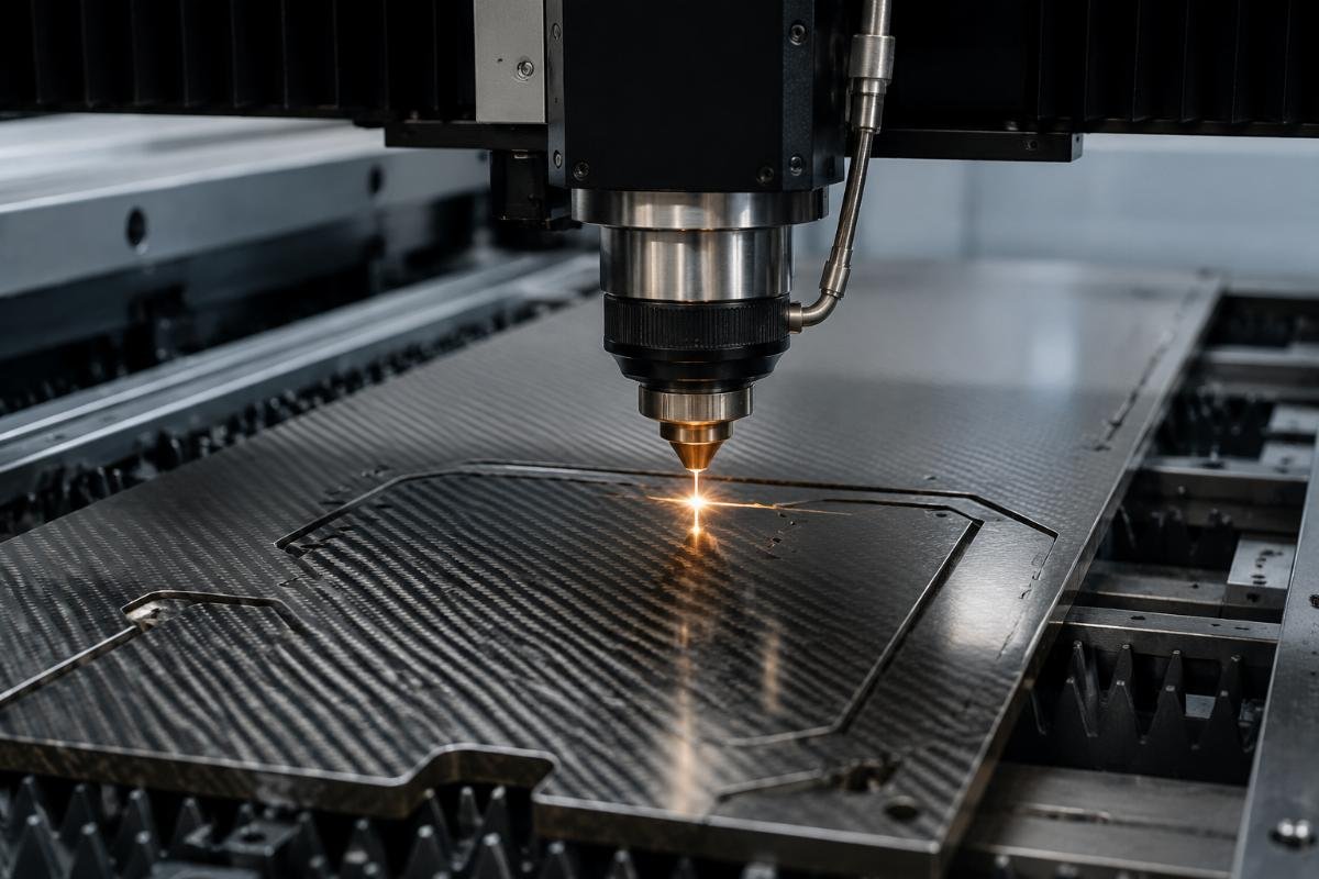
What Material Samples Should You Bring for Testing?
Don't rely on supplier-provided samples. Bring these from your production stock:
Thickness extremes: Your thickest and thinnest material within specified tolerance. If specs say 6mm ±0.5mm, bring 5.5mm and 6.5mm samples. Test both. Cutting parameters that work for 5.5mm may cause over-penetration at 6.5mm.
Fiber direction variation: Cut samples with fiber orientation parallel to cutting direction and perpendicular to cutting direction. Hemp fiber boards especially show different edge quality based on fiber direction relative to blade path.
Aged material: Material properties change with storage time and environmental exposure. If your production cycle means material sits in inventory for months, bring aged samples alongside fresh material. We've seen moisture absorption change cutting behavior significantly6.
What Specific Quality Checkpoints Must Your Test Include?
Don't accept visual inspection as sufficient verification. Implement measurable quality checkpoints:
| Quality Checkpoint | Measurement Method | Acceptance Criteria Example |
|---|---|---|
| Edge fraying | 10x magnification, measure max fiber protrusion | < 0.2mm for visible edges |
| Delamination | Peel test on cut edges | No layer separation visible |
| Cutting depth consistency | Measure uncut fiber depth across all layers | 100% clean cut through all layers |
| Dimensional accuracy | Compare cut part to CAD file | ±0.3mm tolerance |
One customer added a specific checkpoint after experiencing production failures: measure edge quality at the 100th cut, 300th cut, and 500th cut using the same blade. This revealed when blade dulling began affecting their quality standards. They now schedule blade changes at 400 cuts instead of waiting for operator-visible quality degradation.
How Do You Verify Performance Under Production Speed Requirements?
Test cutting speed must match your production requirements. If you need to process 50 parts per hour, calculate the cutting time required and test at that speed. Don't accept demonstration cuts at slower speeds that show perfect quality but don't meet your throughput needs.
Speed testing reveals parameter limits. We've documented cases where cutting quality was perfect at 600mm/min but showed unacceptable fraying at 900mm/min. The customer needed 900mm/min for production efficiency. This discovery before purchase meant they could either accept lower quality, adjust their production speed expectations, or select different equipment.
What Boundary Conditions Determine Whether the Machine Matches Your Needs?
Boundary conditions are the limits where performance becomes unacceptable. These matter more than maximum specs because they define your operational reality.
Material thickness boundary: Test your maximum required thickness plus 10%. If you occasionally process 12mm material, test at 13mm. If the machine struggles at 13mm, you'll have production problems when material arrives at the high end of tolerance.
Continuous operation boundary: Run the machine for 4 hours continuously processing your material. This reveals heat buildup, blade dulling rate, and parameter drift over time. Single-sample tests don't show these issues.
Material variation boundary: Process materials from different production batches. Composite materials have batch-to-batch variation. If the machine requires parameter adjustment between batches, factor this setup time into your production planning.
Should Buyers Choose Dedicated Machines or Flexible Systems for NEV Interior Composites?
This is a risk management decision disguised as an equipment selection question. Neither option is universally better. The right choice depends on your material variety, volume certainty, and tolerance for setup complexity.
Dedicated machines optimized for specific composite types deliver consistent quality with minimal operator adjustment but create production risk if your material specifications change or if you add new lightweight materials to your product line.
When Do Dedicated Systems Make Sense?
Choose dedicated equipment when these conditions apply:
Single material type with locked specifications: If your NEV interior contracts specify Teslin only, with thickness and density locked for the next 3-5 years, dedicated optimization makes sense. You'll achieve faster cutting speeds and better edge quality because every parameter is tuned for that specific material behavior.
High volume production justifies optimization investment: Dedicated systems often cost more initially but deliver lower per-part costs at high volumes. One customer processing 10,000 door panels monthly with hemp fiber boards calculated that dedicated equipment paid for itself in 14 months through faster cycle times and reduced blade replacement costs.
Limited floor space restricts multiple machine installation: If you can only install one cutting system, and 90% of your production is one material type, optimize for that majority. Accept that the remaining 10% may require manual parameter adjustment or slower processing.
What Are the Trade-Offs with Flexible Systems?
Flexible systems handle multiple material types but require more operator expertise and longer setup time. I see these trade-offs most frequently:
Parameter adjustment complexity: Switching from Teslin to hemp fiber boards requires changing blade angle, cutting speed, vacuum pressure, and sometimes blade type. Experienced operators make these adjustments in 15-20 minutes. New operators may need 45-60 minutes and several test cuts. Factor this time into production scheduling.
Compromise cutting quality: Flexible systems optimize for "good enough" across materials rather than "excellent" for one material. If your quality standards accept small edge imperfections, this trade-off is acceptable. If you need perfect edges for visible interior components, flexible systems may not meet standards.
Higher blade replacement costs: Switching between materials with different hardness accelerates blade wear. Customers operating flexible systems report 30-40% higher blade replacement frequency compared to dedicated systems processing a single material type.
How Do You Calculate Risk When Making This Decision?
I've developed a simple framework customers use to structure this decision:
Step 1 - Quantify material certainty:
What percentage of your next 24 months production is confirmed material specifications versus potential changes? If more than 70% is locked specifications, lean toward dedicated systems. If less than 50% is certain, flexible systems reduce risk.
Step 2 - Calculate changeover frequency:
How often will you switch materials? Daily switches favor flexible systems despite setup time costs. Weekly or monthly switches favor dedicated systems because optimization benefits outweigh occasional setup needs.
Step 3 - Assess operator skill level:
Flexible systems require operators comfortable with parameter adjustment and material behavior understanding. If your operator team has high turnover or limited technical training, dedicated systems reduce training requirements and setup errors.
Conclusion
The capability question isn't whether CNC machines can cut lightweight composites—it's whether specific equipment matches your material variations, quality standards, and production conditions. Verify through controlled testing with your actual materials, not supplier promises or spec sheets.
"Lightweight Materials for Cars and Trucks - Department of Energy", https://www.energy.gov/cmei/vehicles/lightweight-materials-cars-and-trucks. Automotive engineering research documents the increasing use of natural fiber composites and synthetic lightweight materials in electric vehicle interiors as part of vehicle weight reduction strategies to improve energy efficiency and driving range. Evidence role: general_support; source type: research. Supports: the adoption of lightweight composite materials in electric vehicle interior applications. ↩
"Dimensional Accuracy and Measurement Variability in CNC-Turned ...", https://pmc.ncbi.nlm.nih.gov/articles/PMC12194426/. Manufacturing precision research indicates that workpiece thickness variations directly translate to cutting depth errors when using fixed-depth cutting strategies, with the magnitude of cutting defects proportional to the thickness tolerance range unless adaptive depth control is implemented. Evidence role: mechanism; source type: research. Supports: how material thickness variations affect cutting depth control in CNC machining operations. ↩
"Optimization of Micro-Texturing Process Parameters of TiAlN Coated ...", https://pmc.ncbi.nlm.nih.gov/articles/PMC9572267/. Research on microporous synthetic substrates indicates that multi-directional fiber weaving patterns require adjusted cutting parameters to prevent fiber displacement during machining operations. Evidence role: mechanism; source type: research. Supports: the structural composition of Teslin materials and how fiber orientation affects machining requirements. Scope note: The source addresses general principles of woven synthetic materials rather than Teslin-specific cutting protocols ↩
"[PDF] Machining Of Composite Materials. Part I: Traditional Methods", https://scholarsmine.mst.edu/cgi/viewcontent.cgi?article=6853&context=mec_aereng_facwork. Manufacturing research on stacked material processing indicates that cutting forces create non-uniform compression through material stacks, with compression decreasing from top to bottom layers, affecting cutting depth consistency when materials have thickness variations or compliance differences. Evidence role: mechanism; source type: research. Supports: how compression forces distribute unevenly through stacked materials during cutting operations. ↩
"Optimizing Wood–Hemp–Sodium Silicate Composites for Strength ...", https://pmc.ncbi.nlm.nih.gov/articles/PMC12843062/. Studies of natural fiber composites demonstrate that mineral content, including silica bodies in plant fibers, contributes to abrasive wear on cutting tools during machining operations. Evidence role: mechanism; source type: paper. Supports: the presence of silica and other minerals in natural fiber composites and their impact on cutting tool degradation. ↩
"The hygroscopic behavior of plant fibers: a review - PMC - NIH", https://pmc.ncbi.nlm.nih.gov/articles/PMC3982556/. Research on hygroscopic composites demonstrates that moisture absorption alters fiber-matrix interface properties and material stiffness, which subsequently affects cutting forces and edge quality during machining operations. Evidence role: mechanism; source type: paper. Supports: how moisture content affects the mechanical properties and machinability of fiber-reinforced composite materials. ↩